Water applications have unique concerns that must be addressed during design of earth retention structures. These may include increased depth of foundation, requirement of free draining backfill materials, rapid draw down and hydrostatic pressure, custom construction techniques, drainage control both surficial and internal, and less common situations such as ice forces, wave action, channel flow rates, or scour potential.
Design Requirements
It is necessary to understand the type of water application one is dealing with when designing an earth retention structure. As a rule of thumb for most water applications, the following minimum design requirements/considerations will apply:
- Minimum one foot embedment to ensure base is protected over time
- Possibly wrapping base and backfill with filter fabric to prevent mitigation of fines into well-draining backfill and gravel base
- Possibly using multiple drainpipes depending on multiple HWLs
- Using well-draining granular soil as backfill to reduce risk of hydrostatic pressure behind wall
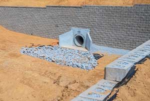
- Increasing depth of drainage column to allow water to flow more freely through system
- Surficial water control by directing water away from wall as much as possible
Application Types
The following is a list of the types of water applications encountered and some additional concerns/design modifications the engineer may consider in each situation:
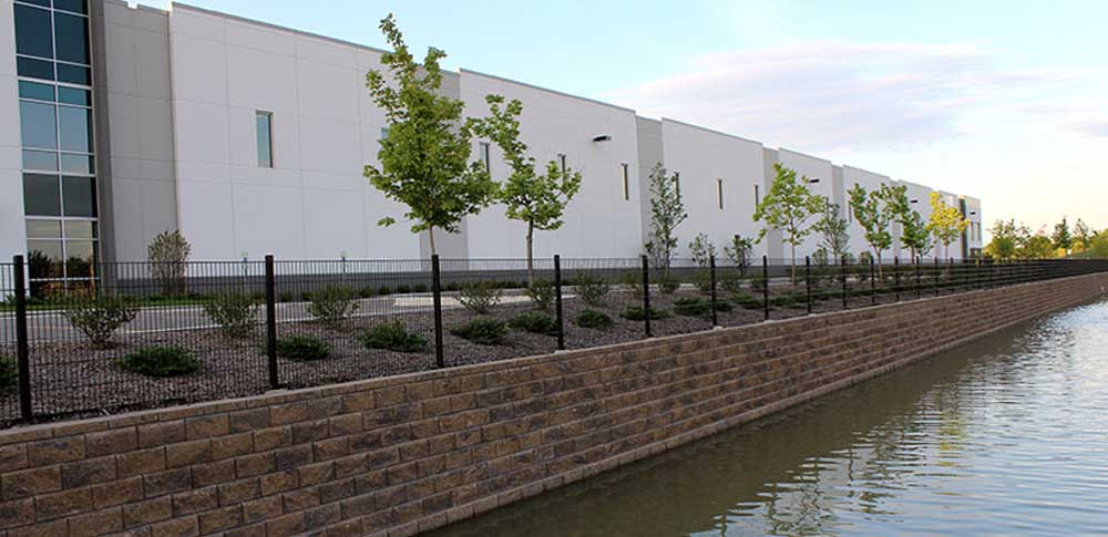
- Retention Ponds – These are meant to permanently hold stormwater runoff on a project site.
- Detention Ponds – These are meant to temporarily hold stormwater runoff on a project site.
- Rapid drawdown
- Bioretention Ponds/Rain gardens/Permeable pavers – Similar to a retention pond but used to slow and treat on-site stormwater runoff though various media by physical, chemical, and biological means.
- Greatly increased depth of embedment to obtain pond capacity and enable filtering through various media
- Shoreline Applications for Lakes – A physical barrier to prevent erosion along shoreline.
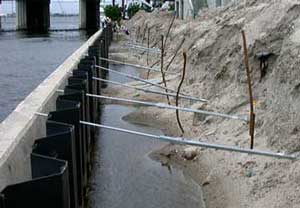
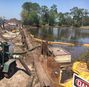
- Dewatering to construct wall
- Wave action
- Ice forces
- 2’ embedment for scour and riprap
- Shoreline for Rivers/Channel Lining – A physical barrier to prevent erosion along embankment.
- Flowrate
- Damage from large debris/ice
- 2’ embedment for scour and riprap
- Rapid drawdown
- Wetlands/High ground water – Water is visibly present or becomes present during excavation in proposed wall location.
- Dewatering to construct wall
- Loose/soft soil with low bearing capacity of base soils requiring sub cut
- Chimney drain/drainage blanket
- Wetland encroachment buffers
While these may be some useful guidelines and items to consider, every site is unique and will have its own unique set of variables that need to be factored into the design.