Weekdays: 8 AM – 4 PM

Retaining Walls

PDEAS, SOIL NAILS & HELICAL ANCHORS…OH MY!

Earth anchors are often used in earth retention designs when geogrid reinforcement is not an option.  But these amazing earth retention solutions come in a variety of shapes and sizes and  it can be overwhelming or intimidating to determine which option is best for your project.  Let us help you down the yellow brick road to success by breaking down the differences between some of the most common earth anchor options available.  Learn more about Percussion Driven Earth Anchors (PDEAs), Soil Nails and Helical Anchors—how they work, their benefits and challenges here:

Percussion Driven Earth Anchors (PDEAs)

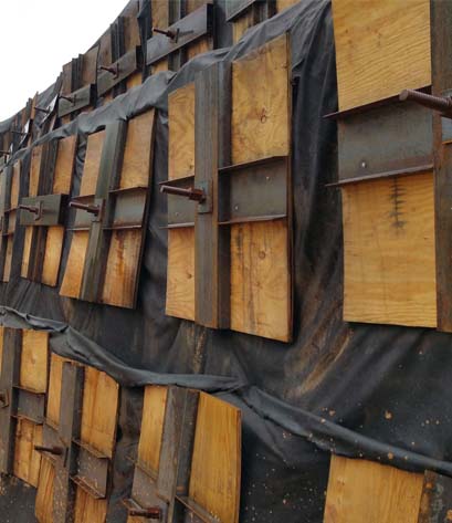
What are they:  Metal rod with a mechanical anchoring system at one end to tie back or stabilize the ground for vertical construction in either temporary or permanent structures. (Examples: Duckbill, Manta Ray, Platypus.)

How it Works:  A PDEA is impact driven by hammering a driving to force the anchor end and rod/cable into the ground.  Once the determined anchoring depth is reached, the rod/cable is pulled back on from the ground surface to engage and rotate the anchor head, commonly referred to as “anchor locked”.  The load required to pull and lock the anchor is monitored with a device called a load locker which is monitored for capacity and is stopped when the anchor has reached the required design capacity.  A bearing plate is then secured to the end of the anchor and distributes the surface load to suffice pullout requirements.

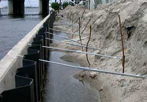
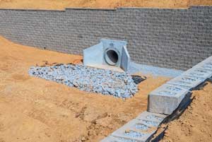
When to use: Erosion Control to anchor different types of geosynthetic & metallic mats and meshes, Retaining Walls, Tree & Pole Anchoring, Landfill Capping, Hurricane Proofing, Slope stabilization, temporary structures and other construction techniques.

Benefits: Often times, the least expensive of all systems and several of them on the market.  Fast/easy to install and corrosion resistant.

Challenges: Least reliable of all systems as soils in the anchoring zone may be uncertain or undefined and anticipated design loads may not be attained.  Often not allowed on DOT projects for permanent structures.

Soil Nails

What are they: There are two different types of soil nails:

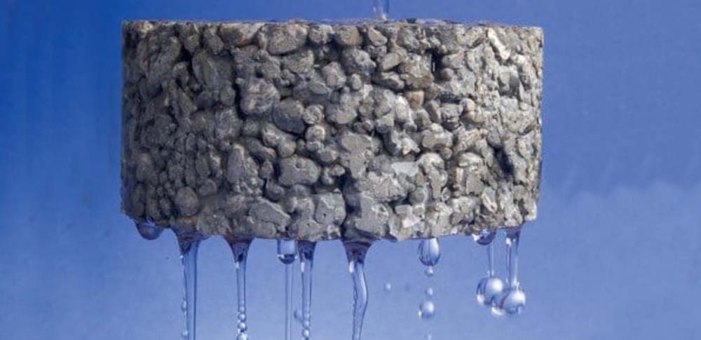
  1. Hollow steel rod with tube inside to that allows grout injection for full length of “nail”.
  2. Solid bar or strand used in open hole installation which is the grout injected to create the nail bonded to the adjacent soil stratum.

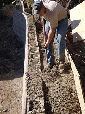
How it Works:  A hole is drilled or rod pushed into the earth at engineered depths and locations.  The soil nail is inserted into the hole.  Grout is pumped into the tube and the rod is slowly retracted as grout fills the hole behind it leaving a “bulb” at the base of the rod and along its sides to act as a nail, securing soil around it.  A plate is then fastened to the end of the nail.

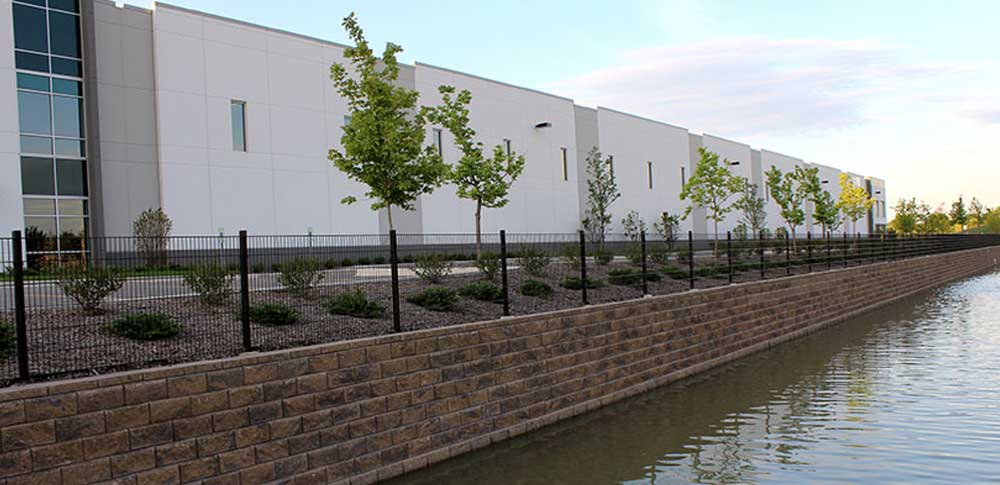
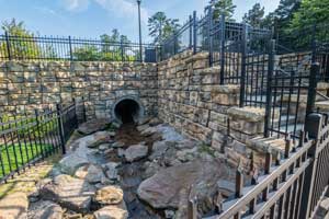
When to use: Erosion Control to anchor different types of geosynthetic & metallic mats and meshes, Tunnels, & Retaining Walls, Slope stabilization, temporary structures and other construction techniques.

Benefits: Very reliable system in engineering terms.  Accepted by agencies such as DOT’s, FHWA, and AASHTO.  Can be done in more confined sites where there are property line or construction easement limitations.  Process is fast and there is no height limitation.

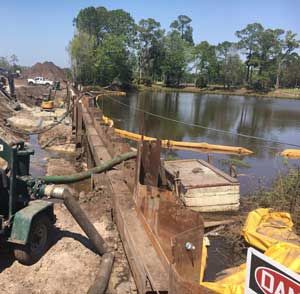
Challenges: Cost can be comparable to Helical Anchors.  Can’t be used in water applications or where ground water is a concern.  Need specialized contactor to install.  Plates and nails can be corrosive, but non-corrosive options are available as well.

Helical Anchors

What are they: Also known as screw anchors or screw piers/piles.  Metal tube anchoring systems that is “screwed” into the ground.

How it Works:  Helical anchors are twisted into the ground using hydraulic rotary equipment that can place the anchor very deep below the ground surface.  The anchor is installed in sections that allows variation in flight sizes with increasing width nearer to the surface to achieve the engineered capacity requirements.  Since the anchors are hollow, they can be filled with grout to increases their frictional capacity.

When to use: If surficial foundation conditions cannot support the load of the intended structure, especially when alternate construction techniques are not feasible for cost or schedule.  Used to repair an existing structure’s foundation that has sustained damage without need for large excavations.

Benefits: Most reliable of all systems in engineering terms.  Several feet can be drilled in a very short amount of time.  Increases bearing of poor or loose with minimal environmental impact.  Can be used to resist vertical uplift forces such as those created by permafrost. 

Challenges: Commonly most expensive of all systems.  Cannot be used in dense/rocky soil types.  Need specialized contactor to install. 

Read more
Water Application Designs

DESIGNING FOR WATER APPLICATIONS

Water applications have unique concerns that must be addressed during design of earth retention structures.  These may include increased depth of foundation, requirement of free draining backfill materials, rapid draw down and hydrostatic pressure, custom construction techniques, drainage control both surficial and internal, and less common situations such as ice forces, wave action, channel flow rates, or scour potential. 

Design Requirements

earth retention water application

It is necessary to understand the type of water application one is dealing with when designing an earth retention structure.  As a rule of thumb for most water applications, the following minimum design requirements/considerations will apply:

  • Minimum one foot embedment to ensure base is protected over time
  • Possibly wrapping base and backfill with filter fabric to prevent mitigation of fines into well-draining backfill and gravel base
  • Possibly using multiple drainpipes depending on multiple HWLs
  • Using well-draining granular soil as backfill to reduce risk of hydrostatic pressure behind wall
  • Increasing depth of drainage column to allow water to flow more freely through system
  • Surficial water control by directing water away from wall as much as possible

Application Types

The following is a list of the types of water applications encountered and some additional concerns/design modifications the engineer may consider in each situation:

  • Retention Ponds – These are meant to permanently hold stormwater runoff on a project site.
  • Detention Ponds – These are meant to temporarily hold stormwater runoff on a project site.
    • Rapid drawdown
  • Bioretention Ponds/Rain gardens/Permeable pavers – Similar to a retention pond but used to slow and treat on-site stormwater runoff though various media by physical, chemical, and biological means.
    • Greatly increased depth of embedment to obtain pond capacity and enable filtering through various media
  • Shoreline Applications for Lakes – A physical barrier to prevent erosion along shoreline.
    • Dewatering to construct wall
    • Wave action
    • Ice forces
    • 2’ embedment for scour and riprap
  • Shoreline for Rivers/Channel Lining – A physical barrier to prevent erosion along embankment.
    • Flowrate
    • Damage from large debris/ice
    • 2’ embedment for scour and riprap
    • Rapid drawdown
  • Wetlands/High ground water – Water is visibly present or becomes present during excavation in proposed wall location.
    • Dewatering to construct wall
    • Loose/soft soil with low bearing capacity of base soils requiring sub cut
    • Chimney drain/drainage blanket
    • Wetland encroachment buffers

While these may be some useful guidelines and items to consider, every site is unique and will have its own unique set of variables that need to be factored into the design.

Read more
No-Fines Concrete

WHAT IS NO-FINES CONCRETE?

No-Fines Concrete or NFC is just as the name implies; a concrete product that is lacking the fine material that provides the smooth texture we all expect in poured concrete.

What is NFC Used for?

  • Perfect for when excavation is needed to be kept minimal.
  • Maximizes the buildable heights of gravity walls.
  • Allows for utilities and property lines to be kept in place behind, or not moved.

No-Fines Concrete Benefits

  • There is less required material to create the same 1M3, this is due to the lack of fines within the mixture allowing less cement to be used.
  • No-Fines concrete exhibits less drying shrinkage compared to typical concrete.
  • 25%-30% less dense, meaning less pressure on the formwork.
  • No special equipment needed to achieve full and proper compaction.
  • No-Fines concrete, being more permeable provides a keen use for this
  • within drain work or areas where draining is needed.

Things to Consider

NFC is a great solution for a wide variety of earth retention projects, but is not with out its drawbacks. Some things to consider before using No-Fines Concrete on your project are:

  • Lacks cohesiveness requiring more time within the framework.
  • There really is not a “standard” form of test other then a visual inspection and trial and error.
  • NFC is more permeable than standard concrete and therefore will require
  • more to keep from allowing water or others such things to flow through.
no-fines concrete installation
Read more

LIMITS OF EXCAVATION

Maximum Allaowable Slope

To protect employees working in excavations, OSHA (Occupational Safety and Health Administration) regulates the slopes at which sites can be safely excavated.  These slopes are measured as the horizontal distance to the vertical rise. The maximum allowable slope is the steepest incline that can is acceptable for the site to prevent cave-ins, while the actual slope is the real slope at which the site is excavated and should not be steeper than the maximum.

In addition to soil and rock types that are commonly used to determine the maximum allowable slope, there are a few additional items to consider when determining excavation limits and wall design.

Existing Structures

Existing structures may affect not only the wall design, but the excavation needed to safely construct the wall.

The Terra

The terrain is important to consider when determining how water moves on the site.  How the site is draining can have an impact on the wall design and the type and location of excavation.

Property Lines

The location of property lines is an important factor to take into account as they may limit the accessibility of the site for both digging and construction of the wall. 

While each site is unique and the excavation limits will vary given the layout and the geotechnical properties of the site, having an understanding of these additional factors and taking them into consideration early in the design phase, can provide the safest and least disruptive way to excavate and ultimately construct a solid wall.

Contact us for more information on excavation limits and how they affect your next project.

Read more

WELDED WIRE FORMS – THE SWISS ARMY KNIFE OF MSE RETAINING WALLS

Did you know we handle welded wire forms? Like the Swiss army knife of MSE retaining walls, welded wire forms may be utilized in a variety of earth retention applications. Some of those applications are:

  • Temporary MSE Walls in lieu of steel shoring
  • Permanent MSE Walls in soft soils
  • Plant-able reinforced slopes
  • Load relief for foundation walls and tip up panel buildings
  • Vegetated shoreline repair
  • Limited site access and staging area

Want to learn if welded wire forms can be used on your next project? Contact us today for design assistance.  Looking for Welded Wire Forms (WWF)? ERS-MidWest stocks both black steel and hot dip galvanized welded wire forms for use in permanent or temporary conditions.

Read more